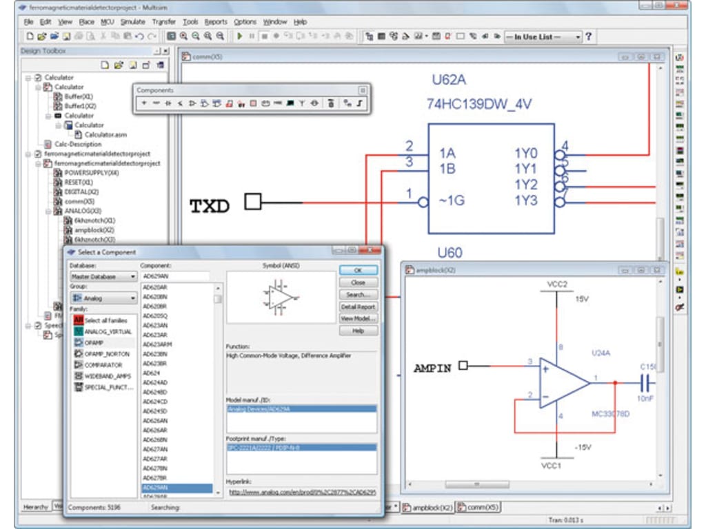
- #MULTISIM COMPONENT LIBRARY UPDATE UPDATE#
- #MULTISIM COMPONENT LIBRARY UPDATE FULL#
- #MULTISIM COMPONENT LIBRARY UPDATE FREE#
#MULTISIM COMPONENT LIBRARY UPDATE FREE#
Oxford Owl is a great free resource because they have a free e- book library designed for young learners. 5% nicotine) About Boosted Mint - Boosted The classic Boosted. It is composed from two layers of phospholipid molecules stacked on top of one another, forming a phospholipid bilayer. Hope this helps someone.Vce textbooks reddit. The caveat to being able to precisely position the parameters as intended by the symbol design is that they will not be auto-positioned upon component rotation.
#MULTISIM COMPONENT LIBRARY UPDATE UPDATE#
(right click component -> Part Actions -> Update Selected From Libraries -> Settings -> Actions -> deselect Preserve Parameter Locations) This allows manually positioned parameters in the schematic to be forced into the parameter position saved in the symbol library. The final location that controls this is more related to Engineering Change Orders. This will now allow components to be placed in a schematic with their parameters placed exactly as saved in the symbol library. (System Preferences -> Schematic -> Defaults -> Primitive List.) In the Primitive List, deselect the Autoposition setting for both Comment and Designator. (this might be an artifact that Altium forgot to remove) The next location that this is controlled by seems to be the most important. (right click parameter -> Properties -> Autoposition) I'm not entirely sure this setting actually does anything as it seems to be overridden by the system preferences. The first is the symbol level properties. The positioning for these is controlled in at least 3 different locations. The key is to first set the exact position you desire for the parameters (designator, comment, etc.) in the symbol and save it. I know this is old, but I had that same problem and and could not find the solution across multiple forums. Either way should work.Įdit 2: Yes, I believe the "Preserve Parameter Visibility" option is new in one of the more recent releases. For some reason I remember this not working correctly for me, perhaps erasing schematic specific parameters, but at a glance it appears to work.
#MULTISIM COMPONENT LIBRARY UPDATE FULL#
Sorry you actually can do a full replace too, just use the other option in the Update From Libraries dialog. You can uncheck the option in the generated ECO.

Use caution though, updating the footprints will reset which footprint is selected for use in the PCB by default.

It works the same way for updating the footprints in the library and then updating from the schematic. It then creates a proper ECO instead of forcing changes you don't want.įor instance if I for some reason wanted to change where the circle was on my test point from top to bottom like this:Īnd then did an update from the library, my schematic would look like this:īut, if I save the library then go back to the schematic and update using Tools->Update From Libraries with the above options, I get this: You can uncheck the box for selected components only or just select the ones you want and update that way. The main problem is when the parameters get updated, because that's when the position gets reset. Then uncheck the option to update parameters: Update from the schematic with Tools->Update From Libraries. However, as changing the graphical symbol and the footprints is the most common change, this should usually work.ĭon't update from the library. If you want to change the base parameters or which library the component is coming from then you're not going to be able to do it. If all you're doing is changing the graphical representation or the footprints then this method works perfectly.


 0 kommentar(er)
